Field report: Ultrasonic flowmeter TUF-2000M

Since my heating system, a water-to-water heat pump, does not offer the possibility to measure or record the water flow of the primary water circuit, I could not estimate whether enough water is being pumped from the extraction well.In addition to having to keeprecords of the flow rate for approval of the system , knowing the water flow rate for this type of system is essential for potential fault diagnosis. In order to keep a better eye on the primary circuit as a potential source of error, I looked around for a way to measure the flow. After a short research, I ended up with ultrasonic flow meters. The principle sounds ingenious at first: two small ultrasonic sensors measure the water flow from the outside via the transit time of the sound. The water circuit does not have to be interrupted for installation, and the fact that the measurement does not affect the flow at all is a major advantage of this technology. The only drawback, the devices are relatively expensive. Still not quite cheap, but affordable, I ended up with the device TUF-2000M TDS-100. Via a serial interface the device can be read out and the water flow can be recorded, more about this in a separate article.
The TUF-2000M can be purchased from about 200€ to about 400€, excluding power supply.
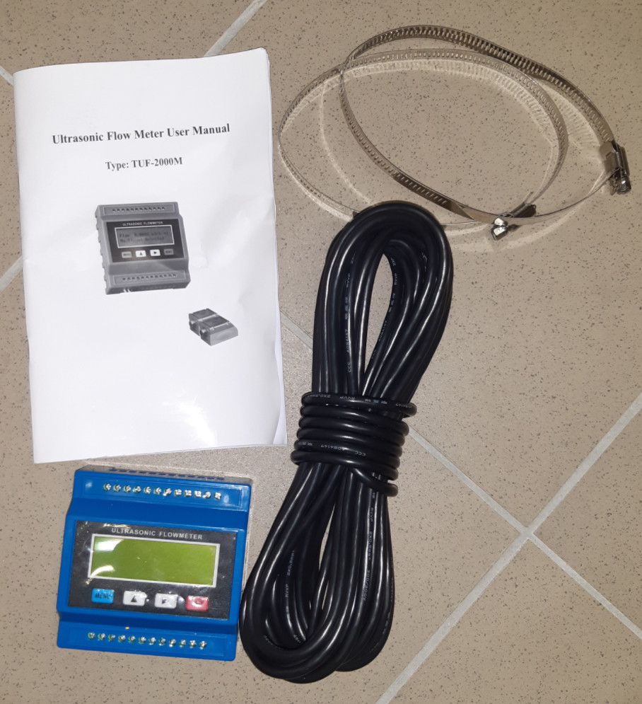
In addition to the picture, the TUF-2000M came with 2 TS-2 ultrasonic sensors.
Power supply
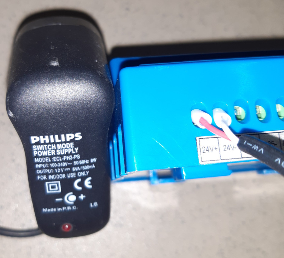
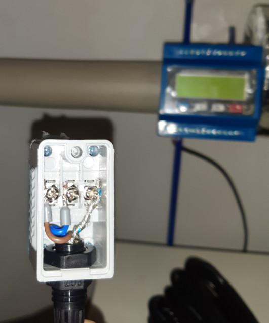
The power supply is not part of the delivery, so I used a normal 12V DC power supply. The power supply came from my rummage box of old chargers. I believe it originally charged Philips LED candles before they ran out of light one day. After years of unemployment, the power supply now has a permanent job again, as a power supply for the water flow meter:
Wiring diagram
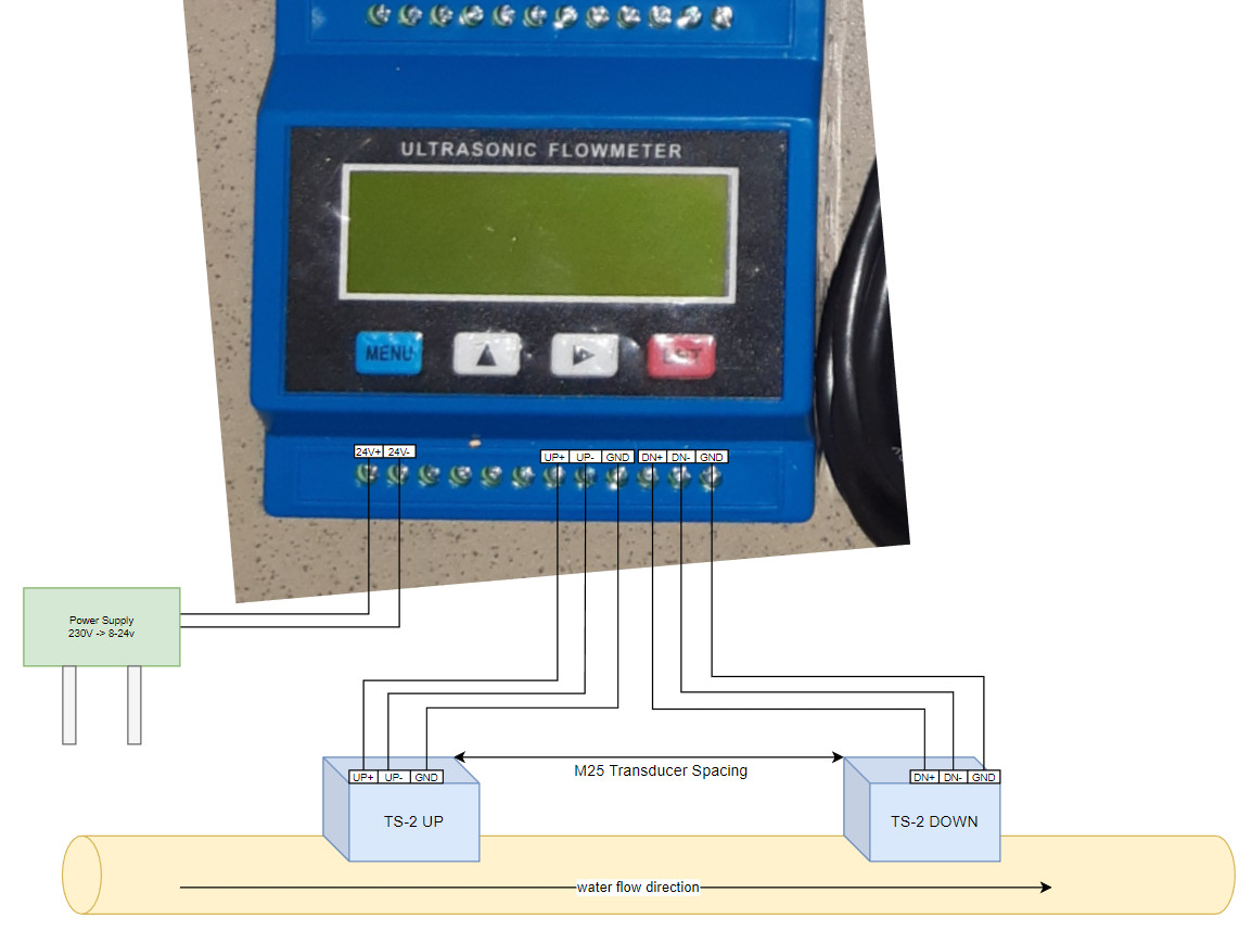
The connections on the flowmeter are well labeled, the wiring is correspondingly self-explanatory:
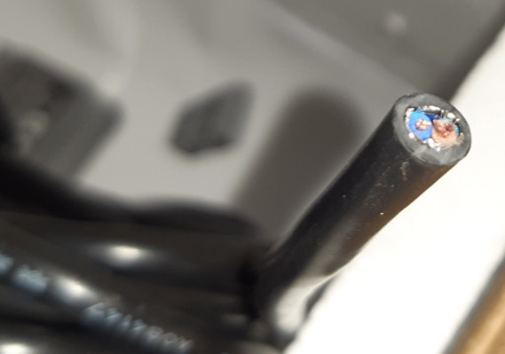
The supplied cable is felt 10 meters long, 2-pole and with shielding:
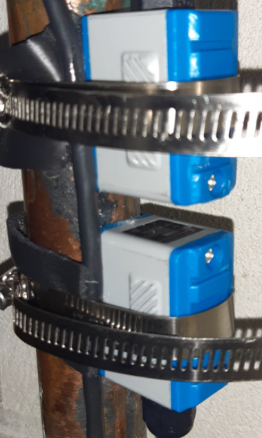
For testing, I initially used short 3-core 1.5mm² electrical cables and cable ties to be able to return all parts of the scope of delivery as intact as possible in case the project fails. A short summary: The electrical cables would have worked and sending them back was not necessary, accordingly I fixed the sensors:
Important: For the ultrasonic sensors to work, some grease must be applied to the underside, I used Vaseline for this. Before the final mounting, the parameters should be set in the device, because the menu item M25 specifies the distance of the sensors on the pipe, see M24 / M25.
Setup
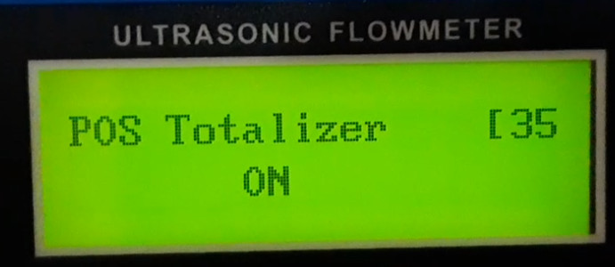
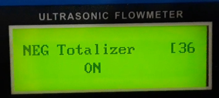
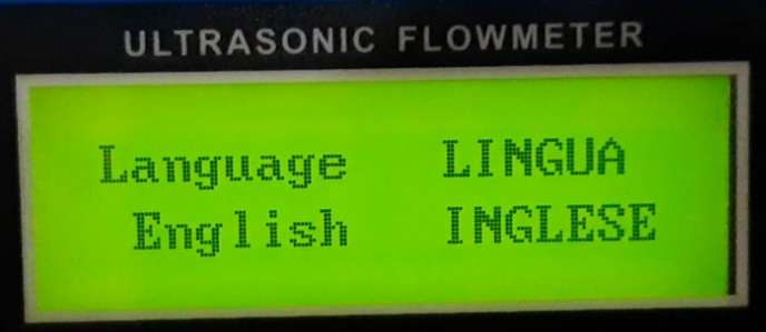
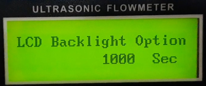
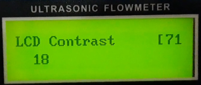
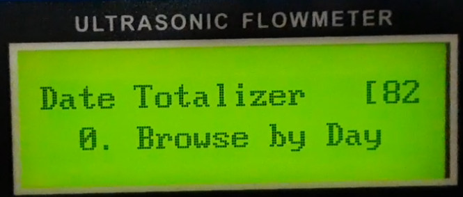
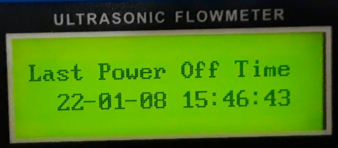
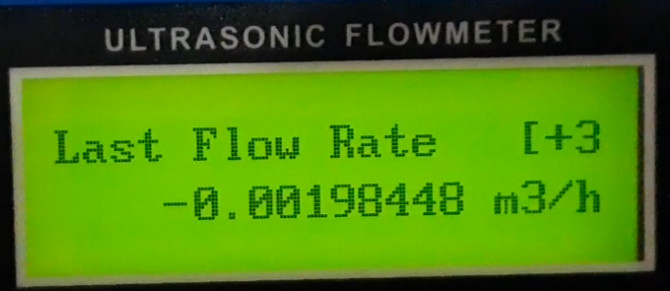
Display indications
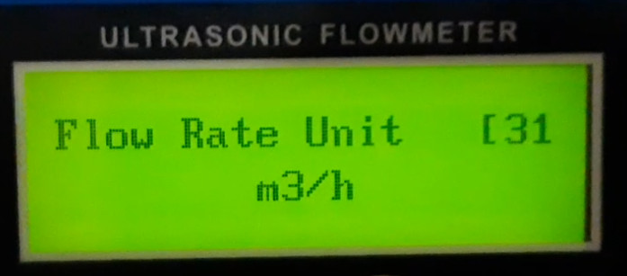
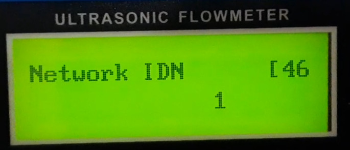
I have clicked through my current settings once using the right arrow key and documented them here. The menu items can also be selected directly by pressing the "MENU" key and entering the number. For the setup of the flowmeter you can start directly with menu item M11.
Overview menu 00-09
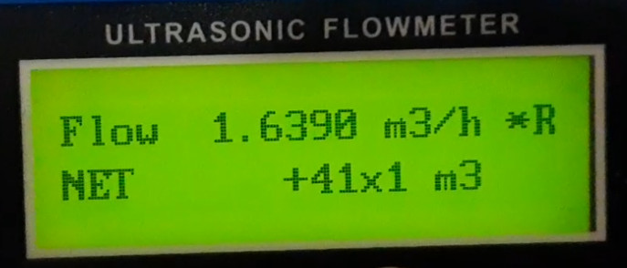
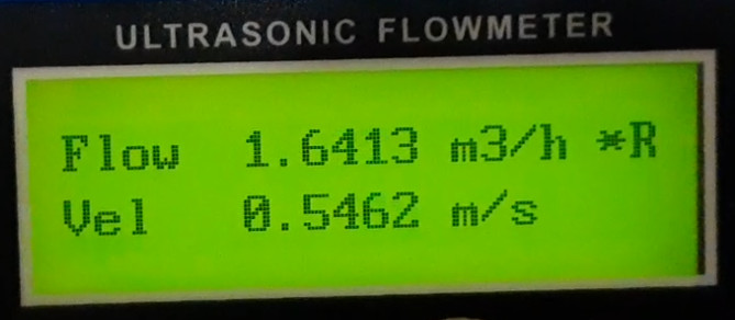
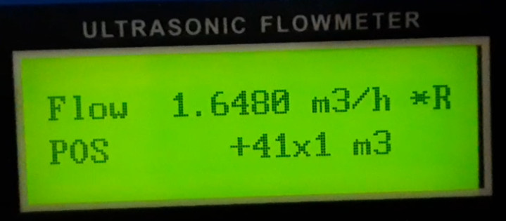
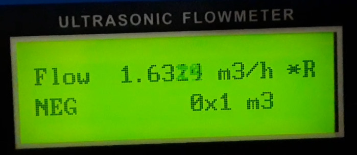
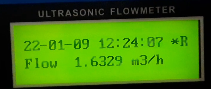
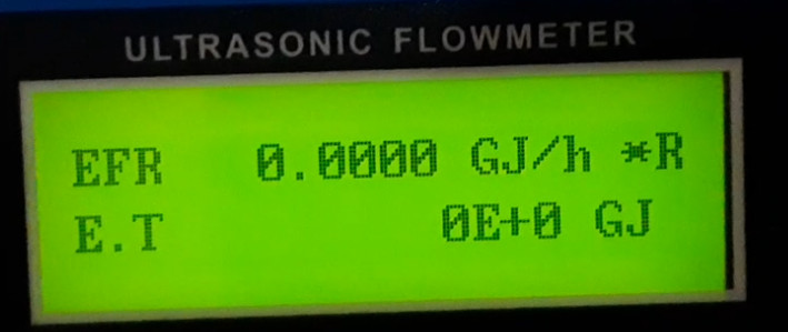
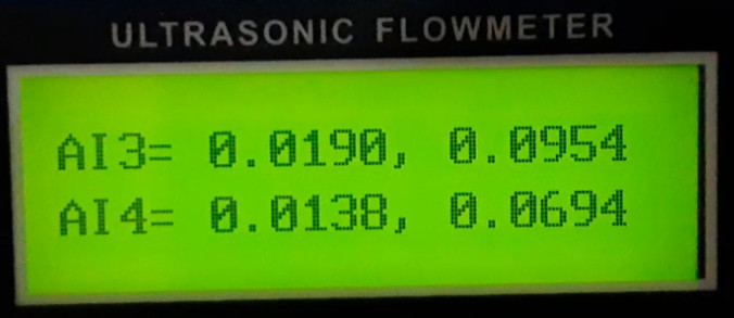
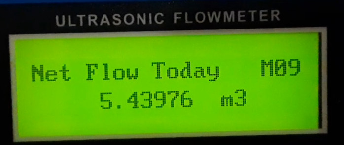
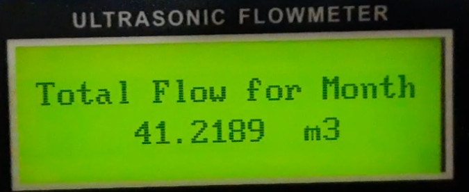
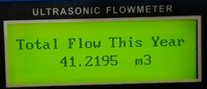
The menu items 00-09 show, provided a correct setup, values for flow, energy and temperature values:
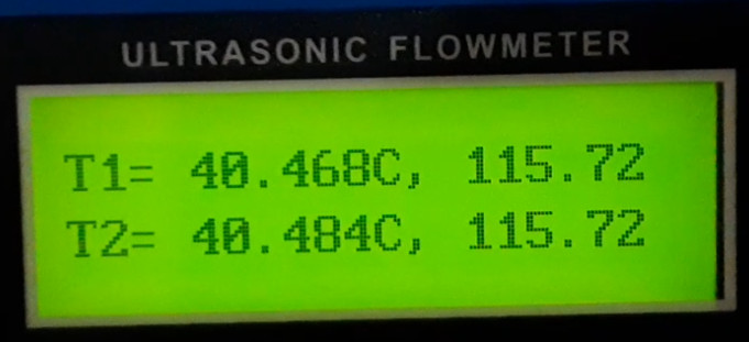
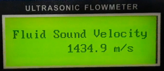
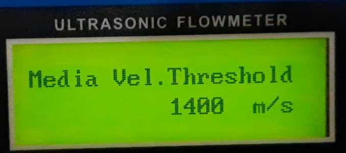
The temperature display of the TS-2 transducer shows with me approx. 40°C with a resistance of 115Ohm, the temperature of the pipe is thereby approx. 11°C. The conversion factor 115Ohm to 40°C would fit the curve of a PT100 temperature sensor: I would conclude that my TS-2 transducer does not have a normal PT100 sensor installed. More important than the temperature is the sound velocity of the fluid (Fluid-Sound Velocity) which for my approx. 11°C water temperature is displayed by the instrument with approx. 1435 m/s: which is plausible for pure water ... (see: menu item 92). So far for me ok, at least I did not get the device for measuring the temperature, respectively it would be possible to connect additional temperature sensors, the values for this appear in the next menu item, with the number 07:
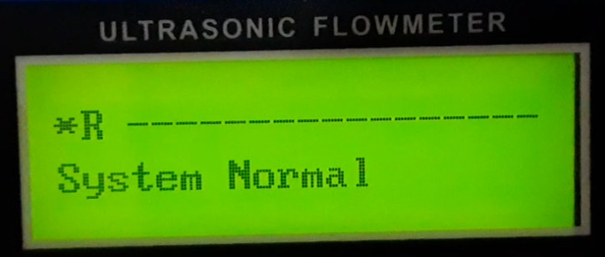
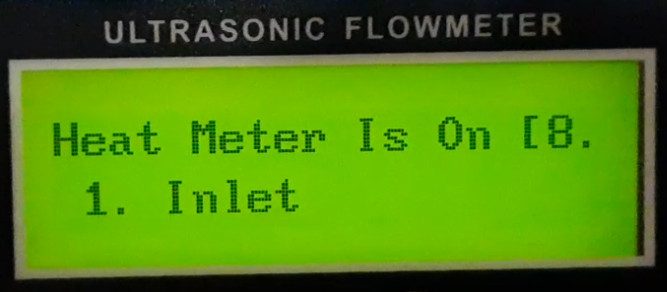
Interesting is also the status in menu 08: Only after I have applied some Vaseline on the flow sensors, this could read out something and the status has changed to "System Normal":
Between M10 and M11 then comes the following display, I guess at this point messages could be transmitted via an interface to the FlowMeter?
Tube Settings Menu 10-16
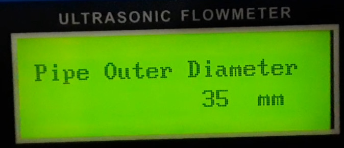
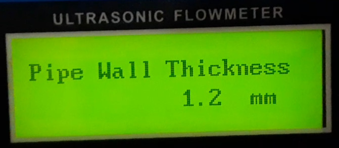
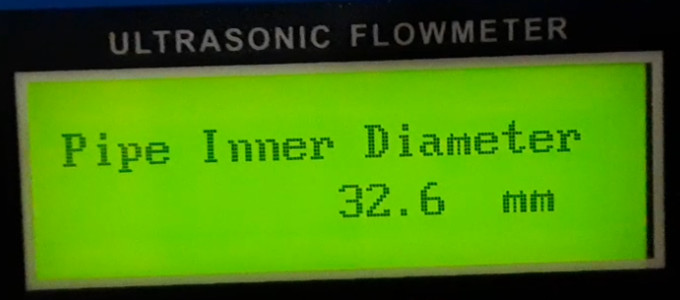
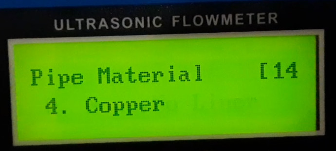
Originally the "Outer Perimeter" was displayed in menu 10, currently the menu jumps directly to Pipe Outer Diameter: M11, which also starts the relevant settings for flow measurement. Relevant for the measurement are the menu items M11 (Pipe Outer Diameter), M12 (Pipe Wall Thickness) and M14 (Pipe Material) in my case it is a copper pipe. The menu item M13 is automatically calculated from M11 and M12.
Sensor Settings Menu 20-xx
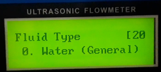
In menu item 20 the type of fluid can be specified, in my case water and with M23 the used ultrasonic sensor has to be set:
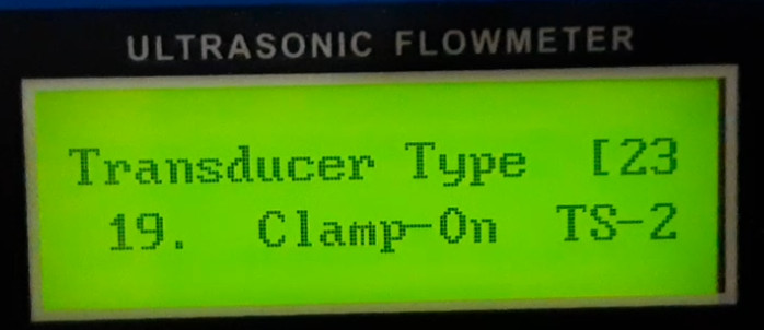
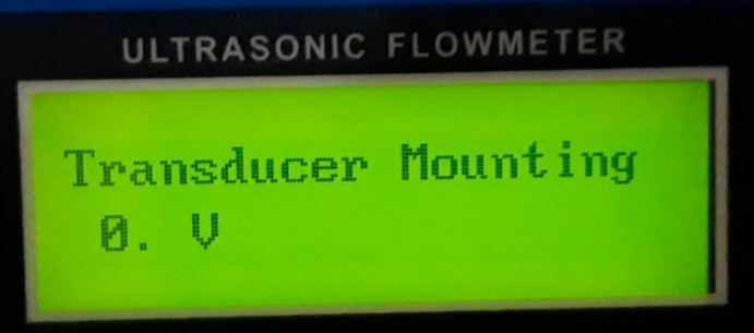
Transducer Mounting is the variant how the sensors are mounted on the pipe. V is the preferred variant for pipes between 15 and 200mm. The sensors are mounted on the same side of the pipe at the distance of the next menu item M25 "Transducer Spacing":
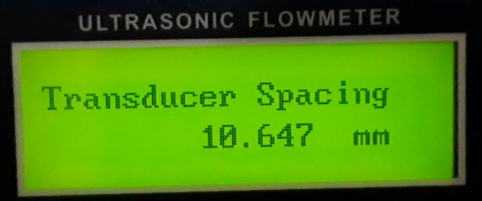

Contrary to my initial assumption, the spacing of the sensors depends on the pipe diameter and the mounting variant and is predefined: The sensors must be mounted according to the value.
Save settings
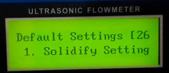
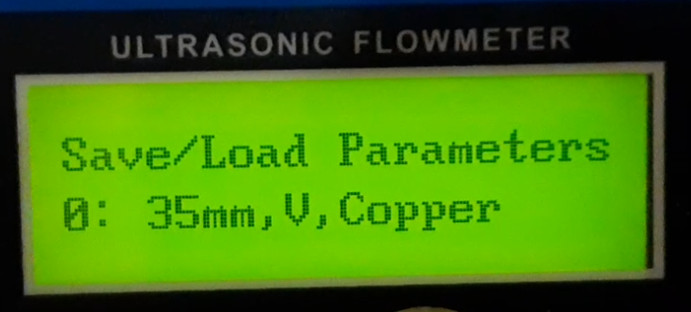
Menu 26 allows to save the current settings so that they are used again after a power failure or restart of the flowmeter. M27 allows to save and load different settings.
M28- ...
Calibrate no flow
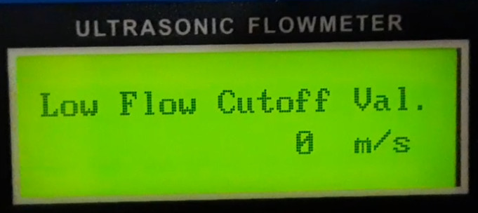
If there is currently no water flow in the pipe, but a flow is still displayed, the flowmeter can be calibrated with menu item 42:
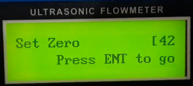
"M42: Set Zero" should therefore only be executed if the liquid in the pipe is not moving. The flow meter counts down a few seconds and should then display values close to 0.
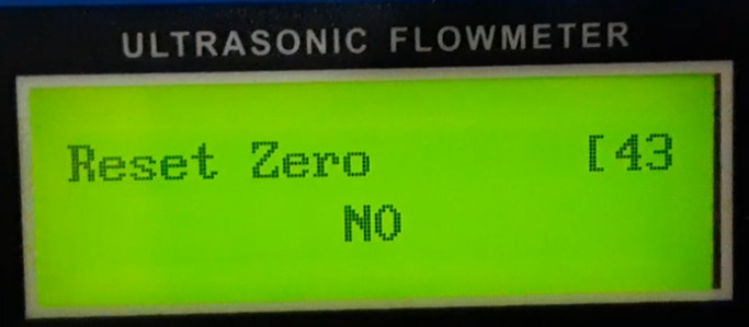
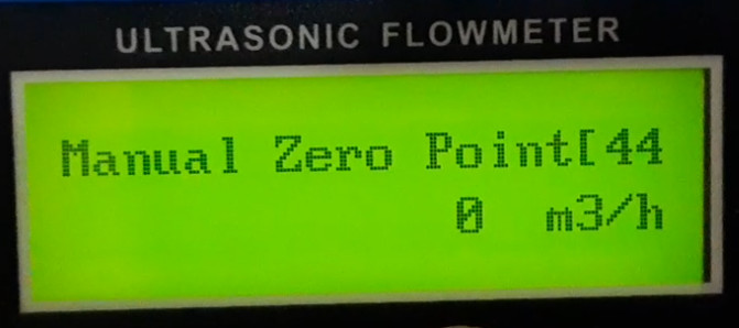
M44 - ...
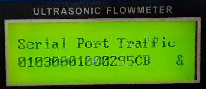
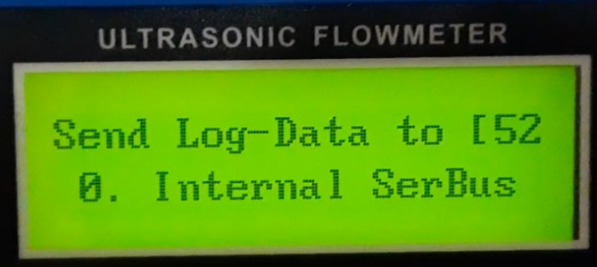
The menu item M49 shows data at the serial port, this is because I have connected an ESP32 to the RS485 to transfer the data via WiFi to HomeAssistant, see: ESP32 Flowmeter - RS485 Modbus
M50 - ...
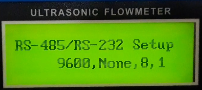
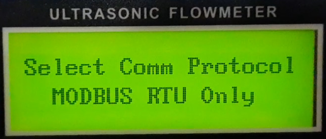
M62 and M63 RS-485
For communication with ESP32 I set M62 (RS-485/RS-232) to "9600,None,8,1" and M62 (Select Comm Protocol) to "MODBUS RTU Only":
M64 - ...
Accuracy
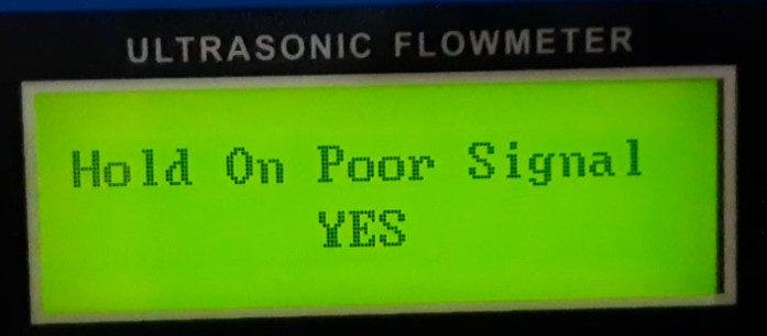
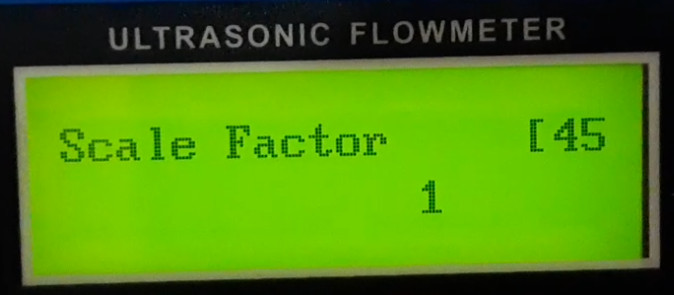
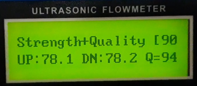
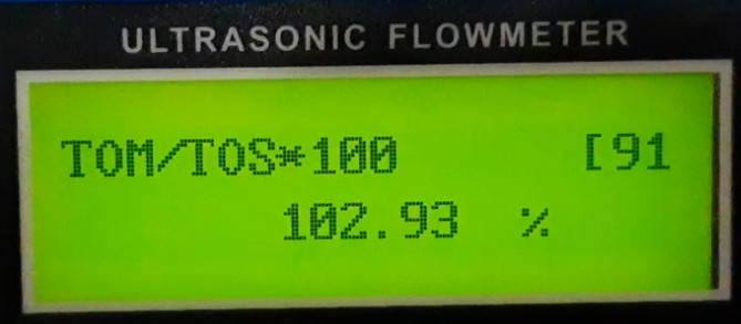
Depending on the distance of the ultrasonic sensors, it shows a different flow rate: If the distance is smaller than the given value, more flow rate would be displayed. With the calculated distance, I have about 103% in menu 91, which is just within the tolerance of 100 +- 3%. If I would decrease the distance, menu 91 would go closer to 100%, the Fluid Sound Velocity would then increase and more flow would be displayed. The accuracy certainly depends on the installation: if the pipe is long enough, the parameters for the pipe diameter are correct, which should then lead to a value in the vicinity of 100% in menu 91. In addition, a signal quality of more than 85% is necessary to get stable values. I only measured the flow rate after some time by measuring the time until a 5 liter bucket was filled with water. The result: The flow meter displayed too little by a factor of about 1.3, which I simply corrected via menu item 45 (Scale factor).
Conclusion
After I applied some Vaseline to the sensors, the flow meter started doing its job relatively quickly. To ensure that the flow meter displays the correct values, it should always be calibrated. For collecting the data via RS485 and an ESP32, see: ESP32 Flowmeter - RS485 Modbus.
ESP32 Flowmeter and RS485 Modbus
As described on the article ESP32 programming, Arduino - install requirements, my first goal was to read out a TUF-2000M Ultrasonic Flow Meter via an ESP32. I found an example for an ESP8266 on the internet: Reading a TUF-2000M Ultrasonic Flow Meter with an Arduino or ESP8266 and https://forum.arduino.cc/t/comunicacion-rs485/698786/2. I described the setup of the TUF-2000M in the following article: Field Report: Ultrasonic Flow Meter TUF-2000M. To be able to read out the TUF-2000M via RS485, it... ... continue reading
 ({{pro_count}})
{{percentage}} % positive
 ({{con_count}})
THANK YOU for your review!
Questions / Comments
(sorted by rating / date) [all comments (best rated first)]
[6 additional Comments in Deutsch]
Hallo,
ich danke am Anfang mal für die Info die zu lesen sind.
Ich habe auch den TUF -2000M mit den Sensoren UP und DW sowie Netzteil 24 V neu zugelegt mit der Anleitung in English und versuche mich mal durchzukämpfen.
Unter Strom aber noch nicht an den Wasserleitungen angeschlossen und getestet. Es sind PVC Leitungen mit 20mm Außendurchmesser.
Noch allgemeine Info, benötige den TUF für Erdleitungen 2 x Vorlauf und 2 x Rücklauf zu bestimmen, das heißt, ich muß die 4 verschiedene Leitungen bestimmen und lokalisieren, bevor ich die durchtrenne muß ich wissen, welche 2 gehören zusammen?
Jeweils Vorlauf und Rücklauf und wie ist die Strömungsrichtung?
Kann mir jemand einen Tipp geben!

mfg Ernst
Thanks for a wonderful write up!
I'm trying to use the sibling of your device, the TUF-2000B, which is in a waterproof case intended for wall mounting.  All the parameters and steps you describe, however, are identical.
Unfortunately, I am finding that for certain pipe parameters and transducer choices I get a negative mounting distance (M25).  Do you know why, and what I can do about it?
A sample: OD=22.2 mm, wall=0.81 mm, liquid=water, transducer=TS-2, mount method=V  result in a negative distance -1.7mm
Changing to method W results in a positive distance = 18.3 mm
Hi, Great guide. I am looking into purchasing a TUF 2000-m. Would anyone with access to the control box be able to find the approximate transducer spacing for a stainless steel pipe with around a 4.5-inch(114.3 mm) and 4-inch pipe diameter (100 mm), Pipe thickness of 0.25-inch (6.35 mm), using a V shape waveform using the TM-1 transducer and no liner? I am trying to get a range of the spacing for the transducers before purchasing the equipment
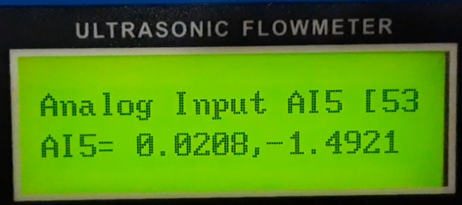
Thank you- very good description.
I am trying to set up my TUF-2000m.
I am having trouble getting a good quality reading.
I have designed a 3d printed clip on adaptor to hold the TS-2 sensors to my 22mm pipe.
This should help with alignment. Keeps orientation yaw/roll/pitch constant, and allows me to micro adjust sensor spacing.
My Q value is poor.

I also note that if you look at the specification for copper pipe and its wall thickness, these have a tolerance.
By trying the extreme tolerance values for the pipe in the TUF-2000 I saw a total sensor spacing variation of 0.57mm.
The actual spacing of the sensors may need to be adjusted to get an accurate reading.
Also note that the reaction of the TUF-2000 is not instantaneous, so calibration needs to be done after the flow reading has stabilized.
I move a bucket under the pipe outlet for 1 minute after the flow rate has stabilized and then measure its volume.
I compare this to the flow rate given by the TUF-2000.
I came here looking for an answer to the temperature sensor.
My TUF-2000 also reads 46C, but I notice this number does not change when I warm up the TS-2 sensors.
The TS-2 sensors do not have temperature sensing in them.
You need to purchase two PT100 sensors (euro 4 each) and wire them to the TUF-2000 using pins 52,53 & 54.
I have yet to get my device to work to my satisfaction- but I keep experimenting!
Good luck with your.
hi. have you set up a zero flow on M42. On my application is a password, do you know the password?
Thank you!
pancu_marius@yahoo.com
created by anonym