Monitor water meter, record consumption: ESP32-Cam

First of all a big thank you to the creators of the "AI-on-the-edge-device" digitizer. The project allows to digitize the water consumption of an analog water meter with a 10 € cheap ESP32 cam. I describe exactly how this works in this article.
Profile:
Software AI-on-the-edge-device GitHub https://github.com/jomjol/AI-on-the-edge-device current version 16.0.0
found 2025-03-22
What are the advantages of a digital water meter?
As a water meter for a house connection, analog water meters are still the norm today. While in the case of an electricity connection, the data is now transmitted to the operator via a smart meter, water consumption must be read and announced annually by the homeowners. The annual reading of the water level is not yet a reasonable reason to record water consumption; rather, a record of water consumption provides a better overview on a day-to-day basis. As an example, an alarm could be triggered in the event of abnormal consumption, possibly allowing a quicker response. As possible triggers I can think of a defective toilet flush, a tap that has not been turned off or in the worst case a leaking pipe.
How can a radio module be added to an analog water meter?
In addition to special add-on radio modules, the "AI-on-the-edge-device" project proves that non-digital water meters can also be read using a camera. In the project, an ESP32 cam is mounted directly above the water meter. The microcontroller periodically takes a photo and recognizes the current meter reading on it using customized text recognition. The meter reading can be recorded on an SD card and displayed via the integrated web interface. In addition, the current meter reading can be transmitted to the smart home via WLAN for better visualization, as an example to Home Assistant.
Required hardware
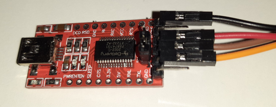
First of all, an ESP32 with camera module is needed for the project. For uploading the image I also bought an USB adapter:

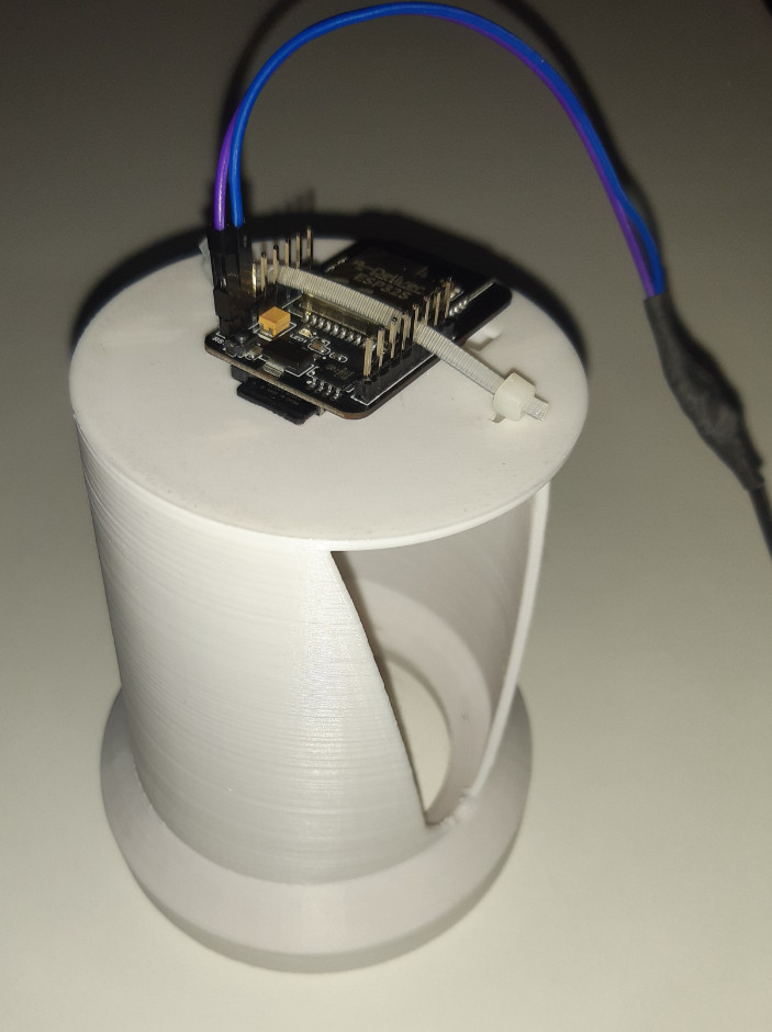
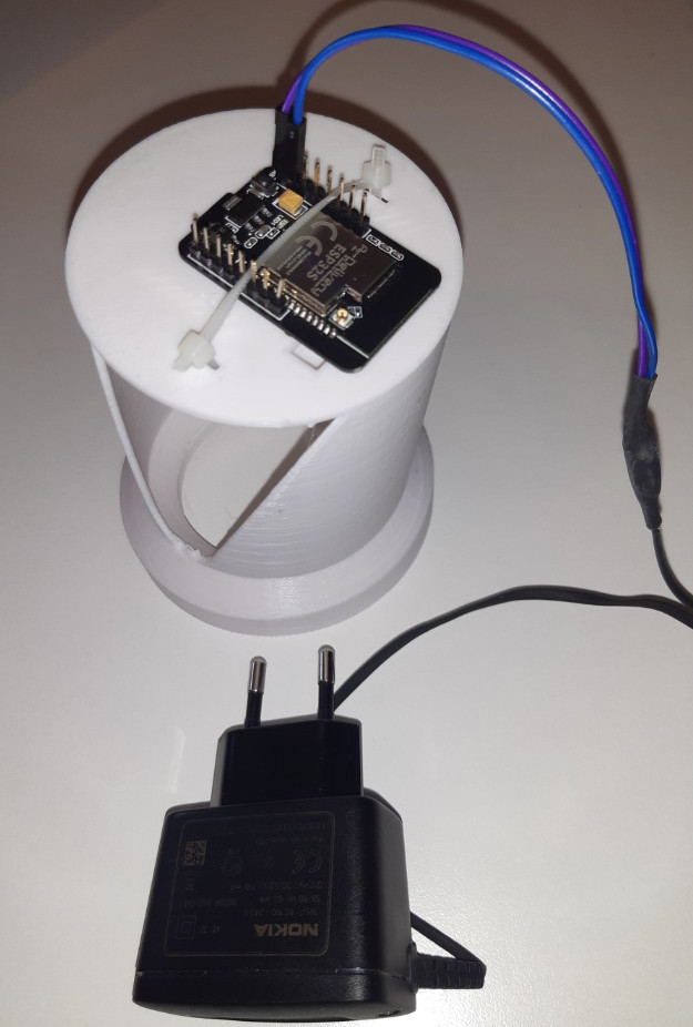
Furthermore, the ESP32 requires a small SD card to store the data and as power supply I use an old cell phone power supply. I attached the ESP with a 3D case from the 3D printer:
Attaching the microcontroller above the water clock.
The existing templates on Thingiverse didn't quite meet my expectations, so I drew my own enclosure. I wanted a model that could be printed in one piece without support and required relatively little filament. I also wanted to be able to use the internal camera and read the water level during operation without having to take the housing down.
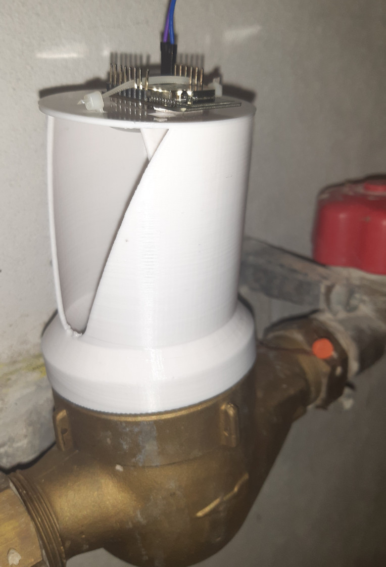
To keep the reflections on the glass within limits, I tilted the housing by 9° and shielded the light of the LED a bit:
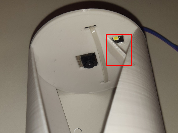
The built-in LED is enough for a decent picture, additional LEDs are not necessary with this model. I have made the template available for download on this site and on Thingiverse, see: Top useful and less useful 3D models..
Focus ESP32-Cam
The focus of the camera is set to distance by default. To get a sharp image at close distance, the camera ring has to be turned out a bit counterclockwise:

Caution: on new cameras, the lens is glued in place, accordingly it is difficult to move it at first. I held the lens in place and used a small flat screwdriver to press it onto a tooth, admittedly relatively firmly.
Step by step: Installing the software
First I connected the ESP32 to the USB adapter:
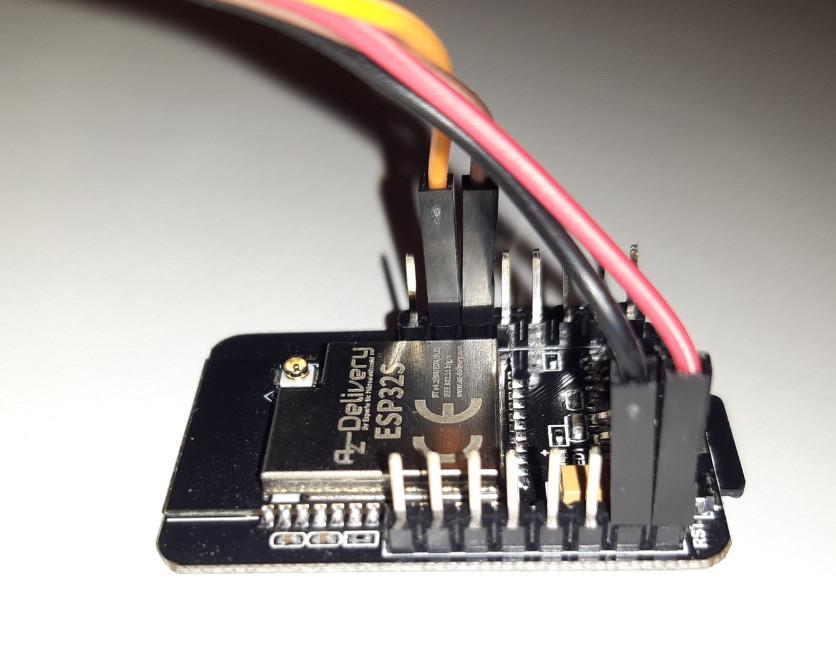
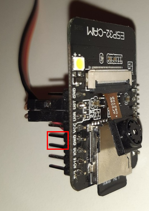
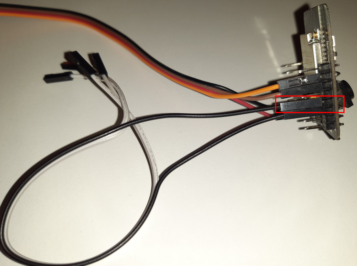
The ESP32 must be put into flash mode by bridging "IOo" and "GND":
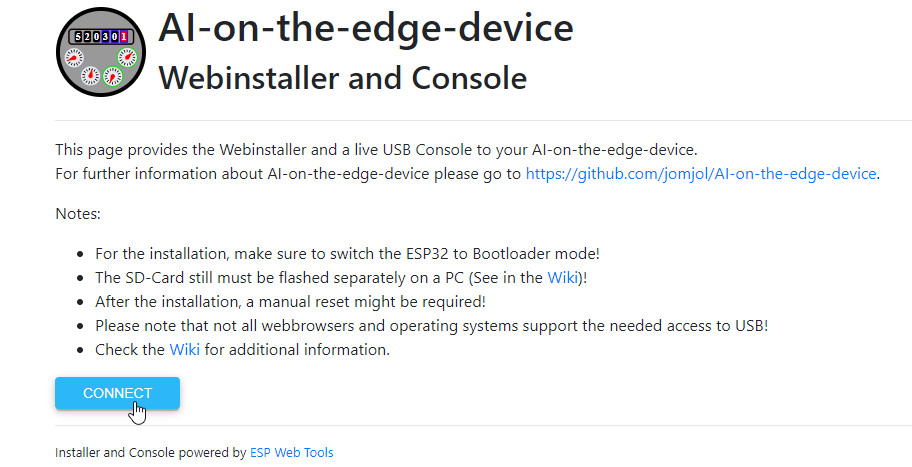
Once the ESP has been wired, it can be connected to the computer via USB and flashed most easily using the web installer in the browser: https://jomjol.github.io/AI-on-the-edge-device/index.html
After the project has been installed, the cable between pin "IOo" and "GND" can be removed . Now we still need the SD card. Preparatory this needs a MBR layout and a FAT32 partition with 32K as allocation unit:

The contents of the SD card can be copied from the GitHub project, subfolder "sd-card" to the SD card: github.com/jomjol/AI-on-the-edge-device/tree/rolling/sd-card.

The folder "sd-card" of the downloaded ZIP archive can simply be unpacked onto the SD card:

For the WLAN connection, the file "wlan.ini" with the WLAN access data must then be adjusted.

To start the ESP I put the prepared SD card into the ESP and connected a 5V power supply, in my case an old NOKIA charger:
The LED on the ESP32 signals the boot process. If it blinks permanently, something is wrong with the SD card. If the boot process was successful, the ESP connects to the WLAN:
- Continuous fast flashing: The SD card is not working.
- 5 x fast flashing (< 1 second): Connection is still down
- 3 x slow flashing (1 second on/off): WLAN connection established
After the ESP has connected via the stored WLAN access data, it fetches an IP address from the DHCP server. A look at the router tells us the IP address for access, alternatively the address can be found out as follows: Find IP addresses on the network, even if their firewall is enabled.
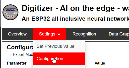
If the IP address is called in the browser after starting the ESP, a setup wizard of the Digitizer appears first. The first step of the wizard is to create a reference image. The reference image will later be used to define the ROIs (Regions of Interest), i.e. the areas from which the meter reading should be taken. The"Aligment Marks" are arbitrary marked areas on the meter so that the digitizer can adjust the image at each reading. The ROIs consist of Digital ROIs, which are the numbers on the meter, and Analog ROIs, which are the pointers. First the digital ROIs: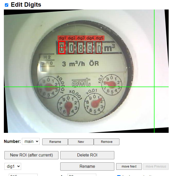
I simply created these sequentially dig1 to dig5. The analog ROIs are the clocks, also here ana1 to ana4
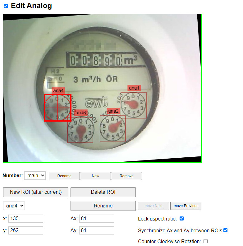
ana1 is for me the first m³ decimal place x0,1, ana2 then x0,01 and so on.
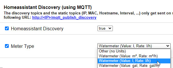
Setting to liters/h and not m³/h
At the beginning I had the default setting with m³/h. After I can imagine more with liters, I started to convert m³ to liters in Home Assistant, duplicating all values. At last I discarded the original values and changed the digitizer to liters:
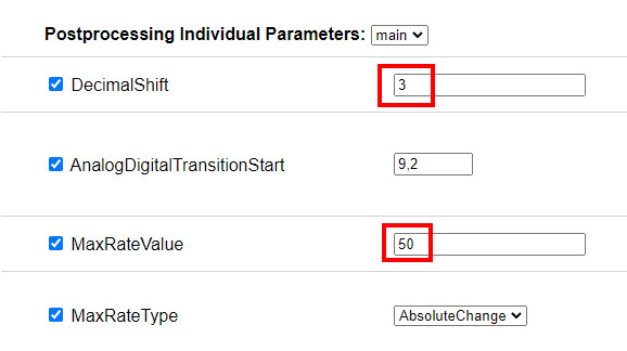
Incorrect values when changing from 9 to 0.
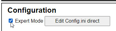
At first, the values were read correctly, but then I had the problem that when I changed from 9 to 0, the digital numbers already showed a higher number. The decimal places from the analog clocks were simply added with the digital values, accordingly for example from 889,9 then 890,9. Remedy is the following settings: "dig-class11_1600_s2.tflite" and "CheckDigitIncreaseConsistency" in "Expert Mode":
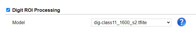
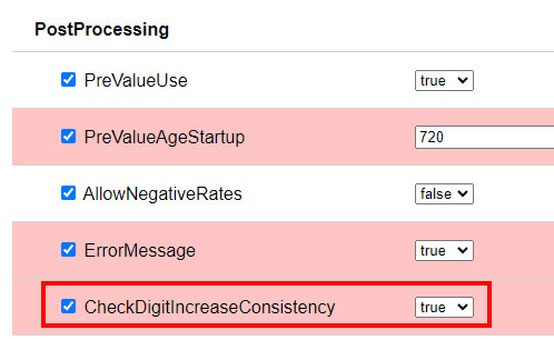
"CheckDigitIncreaseConsistency" uses, after a change from 9 to 0, the previous value for the next higher powers of 10.
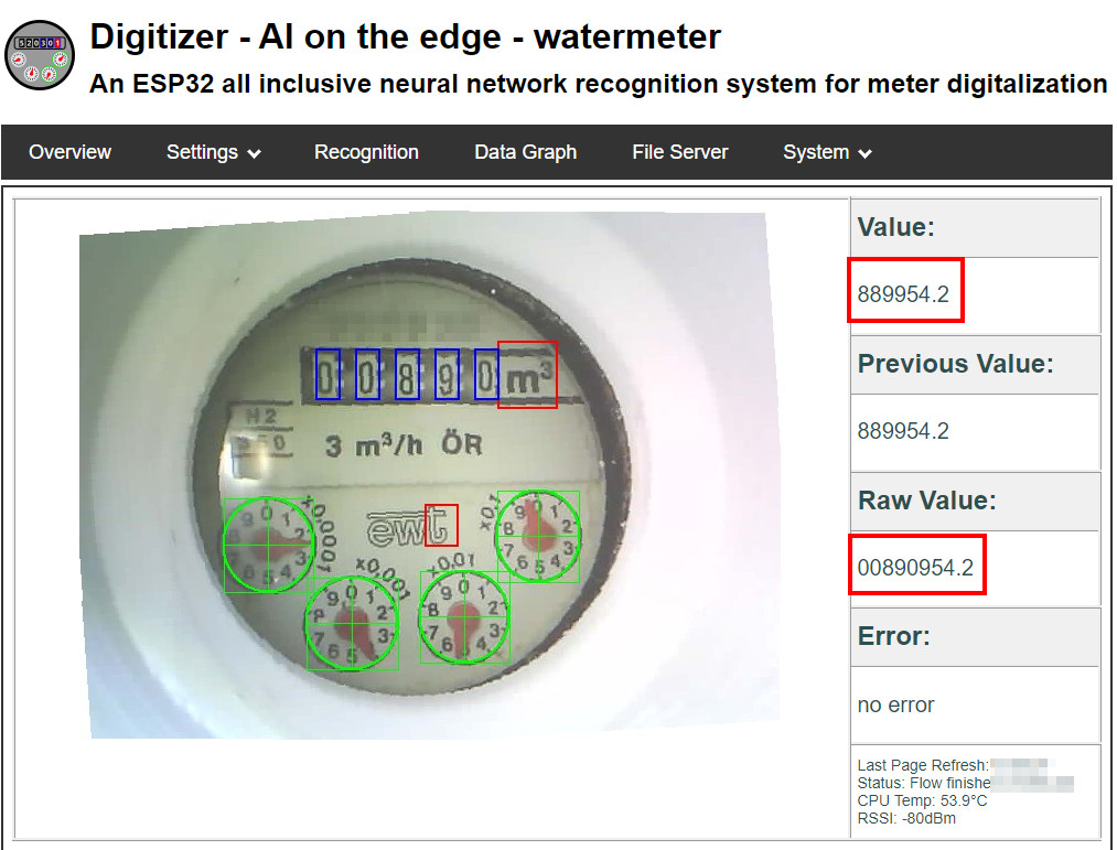
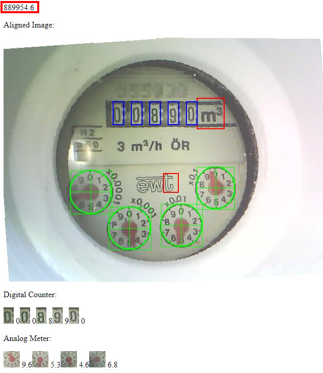
Here is a concrete example: The meter recognizes the correct meter reading of 889954.6 due to the previous value and not the read digital numbers and analog values, which without"CheckDigitIncreaseConsistency" would result in thewrong value: 890954.6:
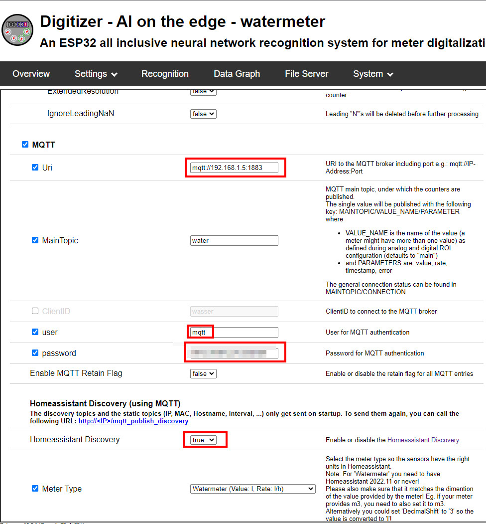
Data MQTT -> Home Assistant
The digitizer can transfer data to Home Assistant using MQTT. This requires an MQTT broker, see: MQTT - Broker : Docker Setup and HA - MQTT Integration
Update: 'Initializing (delayed)'
During the last update to version: v15.3.0, I had the problem that the ESP got stuck in an endless boot loop. I was able to solve the problem by writing a new SD card with the current files of the Git project and performing the configuration again.
Conclusion - Does the digitizer pay off?
Admittedly, I had no need to record water consumption at first. At first, the project itself fascinated me, especially since it pretty much exhausts the technical possibilities of the ESP32 cam. The time needed for the setup is manageable and also the costs for the ESP32-Cam are more than ok. So yes I can fully recommend the project.
 ({{pro_count}})
{{percentage}} % positive
 ({{con_count}})