Control heating: PV surplus with ESP32 & Home Assistant
After around 20 years, I was able to use Home Assistant and an ESP32 to take control of my heat pump and control it. Combined with the performance data of the PV system, Home Assistant is able to use the PV surplus as directly as possible for heating and thus increase self-consumption:
Screed as buffer storage: heating in the afternoon for the next day?
Thanks to the very inert underfloor heating, the heating can be deactivated for a few hours without affecting the room temperature. The screed has enormous storage potential and outperforms a typical buffer storage many times over. Ideally, the heating is no longer active after sunset, which means that the PV system battery can be used purely for household electricity in the evening and at night.
Probably works with any heating system: Fake the temperature with ESP32 ...
As described, my heat pump is over 20 years old and has neither a Smart Grid Ready (SG Ready) interface nor any other way to manage the control system. A look at the documentation for the heating control system revealed to me that the temperature sensors for the boiler and buffer tank are PTC resistors, simple resistors that change with the temperature. This gave me the idea of using other resistors to simulate the buffer tank and boiler temperature. It was important to me that the heating continues to work even without Home Assistant. So I continue to use the built-in PTC temperature sensors and replace them with a low resistance value for switching on and a high resistance value for switching off. Initial attempts with a digital potentiometer were not successful. In the end, I resorted to simple relays and fixed resistors.
Retrofitting Smart Grid Ready (SG Ready) directly or with resistors?
For a heater with SG-Ready interface, the relay board used here could alternatively also be used directly for switching the SG-Ready states; a 2-channel relay board would be sufficient for this. The SG-Ready label defines four operating states for controlling the heating, simplified here:
- Operating state 1 (relay switching state: 1:0): Operation of the heat pump blocked for a maximum of two hours per day
- Operating state 2 (relay switching state: 0:0): Energy-efficient normal operation
- Operating state 3 (relay switching state: 0:1): Switch on heat pump more than usual: Switch-on recommendation
- Operating state 4 (relay switching state 1:1): Actively switch on heat pump
If the heat pump does not have SG-Ready, similar functionality can be implemented with resistors. As described here, considerably more operating states are possible when using resistors than with SG-Ready: e.g. differentiation between heating and hot water:
Supplementing the heating control: ESP32 and 4-channel relay board + Resistors
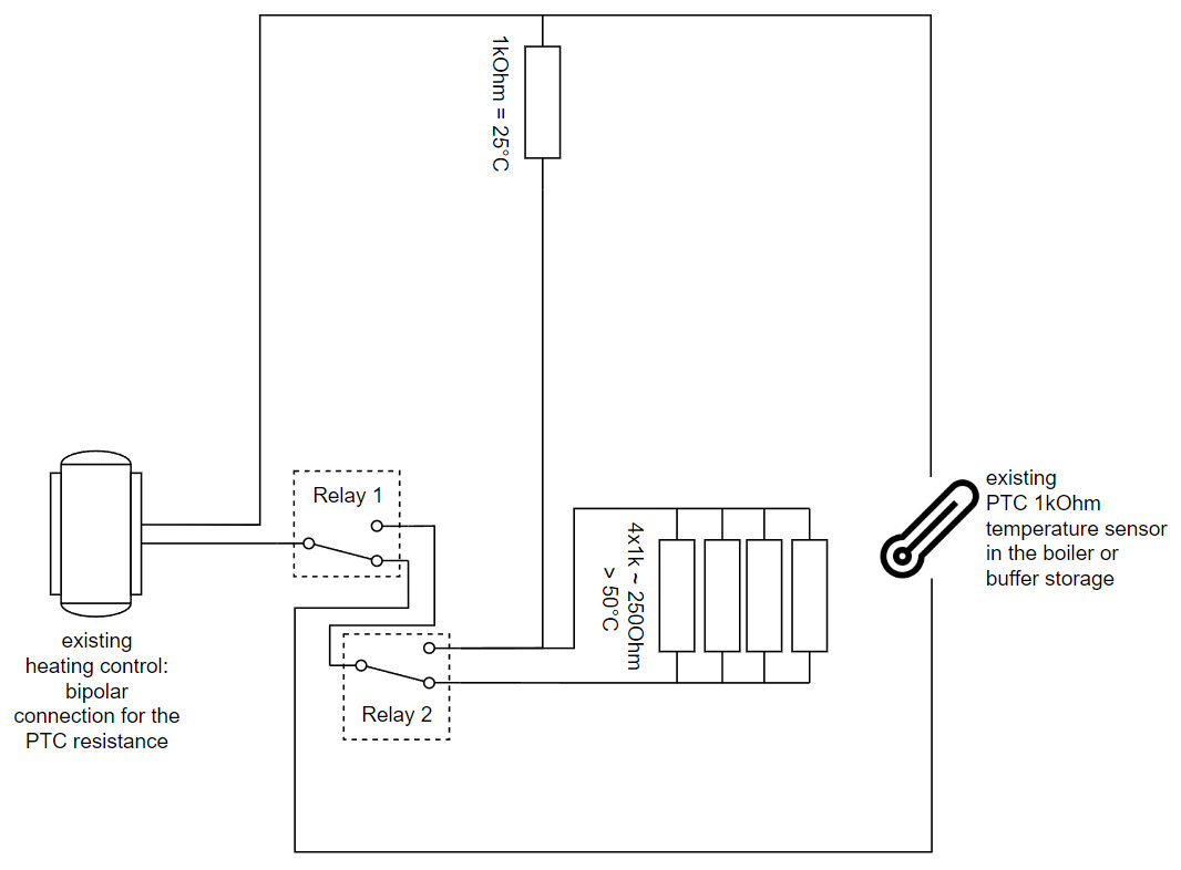
I was already using an ESP32 to monitor the temperature values of the boiler and buffer tank in Home Assistant. By adding a 4-channel relay board, I can use 2 relays to control the hot water and 2 relays to control the buffer tank: Relay 1 and 2 will be for the boiler and Relay 3 and 4 for the buffer tank. I have 1kOhm available as resistors, which corresponds to a temperature value of 25°C with the installed PTC temperature sensor. A value of 1.25 kOhm would already mean over 50°C: similar to a heated boiler. Since I didn't have a 250 Ohm resistor to hand, I used 4 1kOhm resistors in a parallel circuit for the boiler. Here is the schematic diagram for the hot water relays 1 and 2:
If the two relays are not active, the original PTC temperature sensor is used. Activating the first relay interrupts the PTC and replaces it with the optional resistors, which corresponds to a temperature of over 50°C and deactivates the hot water heating. If I switch on the 2nd relay, the resistors for the 250Ohm value are bridged and the remaining 1kOhm resistor simulates 25°C for the heating: Time for hot water preparation.
The circuit therefore enables 3 states for the boiler
- previous automatic operation with the PTC of the heating (relay 1 off + relay 2 off)
- Deactivate heating (relay 1 on + relay 2 off)
- Activate heating (relay 1 on + relay 2 on)
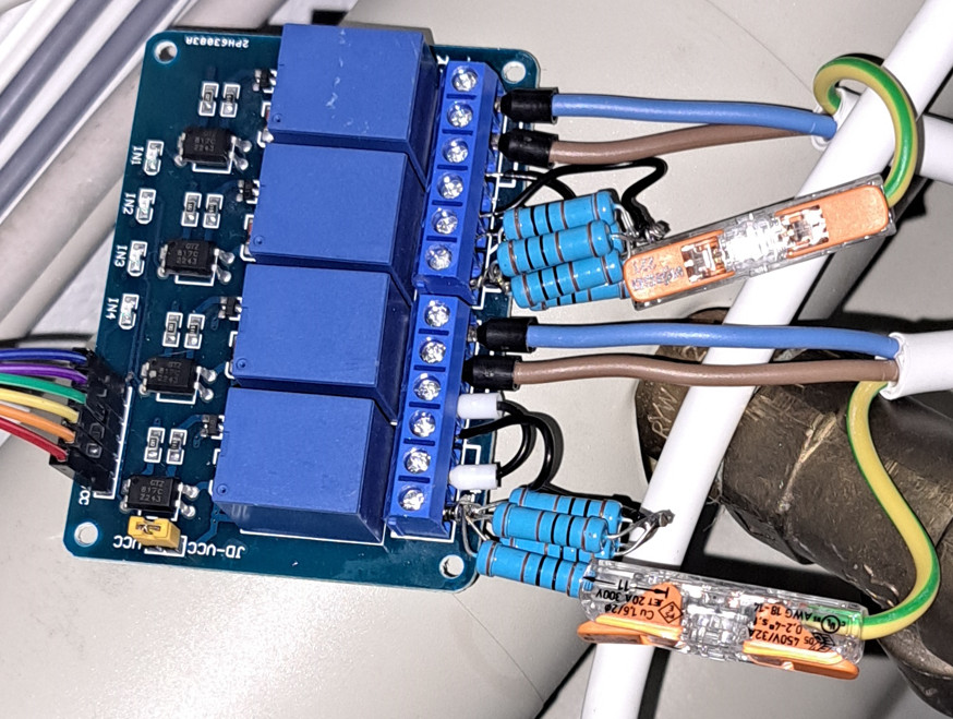
Here are the 4 relays: For boiler and buffer tank: The three-pole cables: yellow-green, blue and brown lead to the existing PTC connection cable.
This is working so far for the hot water. For the heating, the simulated 25°C is too high, so I have adjusted the resistors in the buffer tank as follows: I replaced the 1kOhm resistor with two 470 Ohm resistors, which gives 940Ohms and corresponds to a temperature of 17°C. An additional 300 Ohm resistor results in 1.24 kOhm, which corresponds to a temperature of just over 50°C.
Structure of the control unit and necessary sensors
First a word about my heating system
The three-phase compressor of the old groundwater heat pump only has the two operating states on and off. When the heating is switched on, the pressure rises gradually, whereby the power consumption climbs to a maximum of 4.5 kW depending on the target temperature. An integrated buffer tank is only used for hydraulic decoupling. Heat is supplied to the underfloor heating system via circulation pumps that flow through the buffer tank. The heat pump is activated as soon as the temperature in the buffer tank falls below a certain value and switches off when a set temperature is reached. Technically speaking, loading the buffer cylinder is therefore similar to hot water preparation, with one small difference: the pressure and therefore the target temperature is adjusted using a stored heating curve and an external temperatur sensor.
Required hardware: Requirements
My setup combines the information in the following articles:
- Hardware for Home Assistant and Installation, see: Hardware for Home Assistant? Variants: HAOS vs. Docker
- ESP Home and ESP32 microcontroller, see: Home Assistant + DIY microcontroller + ESP Home (Docker)
ESP32 in addition to the heating control + minimum logic
I have not integrated the ESP32 microcontroller directly into the heating control system, nor has it replaced it. Instead, I have built the ESP32 microcontroller around the existing control system: with its own sensors and its own relays for manipulating the existing heating control system. Dozens of cables lead from the ESP32 for the heating (over)control system to several temperature sensors: installed at various points in the heating system and the house:
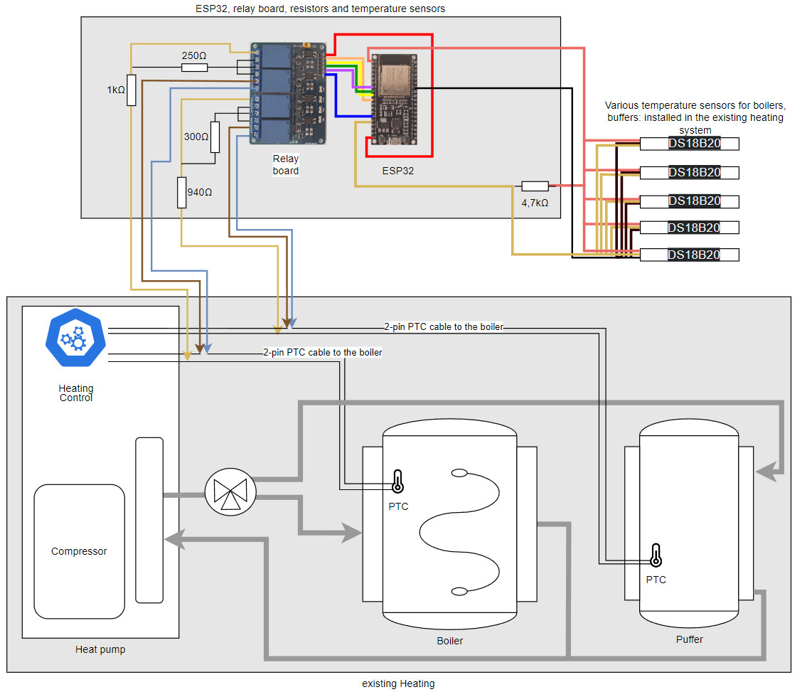
Here is a rough overview of the main components (in addition to Home-Assistant, ESP-Home and an ESP32):
- DS18B20 temperature sensors for heating and outside temperature, see: DS18B20 - Temperature sensors in ESP-Home
DS18B20 temperature sensors installed:
- directly in the heat pump in the heat exchanger
- Boiler
- Buffer tank
- ...
- DHT11 temperature sensors for certain living areas: ESPHome: Temperature and humidity sensors DHT11/22
- Relay board for controlling the heating: Relay Board ESP32 - ESPHome
- Relay1: simulate hot water temperature: without Relay2: hot water
- Relay2: Fake cold water
- Relay3: Fake buffer tank temperature: none Relay4: Hot buffer tank
- Relay4: Fake cold buffer tank
I have put together the complete ESP Home project for the ESP as follows:
esphome:
  name: heating

esp32:
  board: esp32dev
  framework:
    type: arduino

# Enable logging
logger:

# Enable Home Assistant API
api:
  encryption:
    key: "???"

ota:
  platform: esphome
  password: "???"

wifi:
  ssid: !secret wifi_ssid
  password: !secret wifi_password

  # Enable fallback hotspot (captive portal) in case wifi connection fails
  ap:
    ssid: "Heating Fallback Hotspot"
    password: "???"
  on_disconnect:
    if:
        condition:
          switch.is_on: relay4
        then:
          - switch.turn_off: relay3
          - switch.turn_off: relay4

captive_portal:

one_wire:
  - platform: gpio
    pin: GPIO13
    id: hub_1

# Relais
switch:
  - platform: gpio
    pin: GPIO32
    name: Relay-heating-water-fake
    id: relay1
    inverted: true
  - platform: gpio
    pin: GPIO33
    name: Relay-heating-water-kalt
    id: relay2
    inverted: true
  - platform: gpio
    pin: GPIO25
    name: Relay-heating-buffer-fake
    id: relay3
    inverted: true
  - platform: gpio
    pin: GPIO26
    name: Relay-heating-buffer-kalt
    id: relay4
    inverted: true

# Individual sensors
sensor:
  - platform: uptime
    name: heating.uptime
  - platform: dht
    pin: GPIO23
    model: DHT11
    temperature:
      name: "Kitchen.temperature"
      id: Kitchen_temperature
    humidity:
      name: "Kitchen.Humidity"
  - platform: dht
    pin: GPIO1
    model: DHT11
    temperature:
      name: "Livingroom.temperature"
      id: Livingroom_temperature
    humidity:
      name: "Livingroom.Humidity"
  - platform: dallas_temp
    one_wire_id:  hub_1
    address: 0x???
    name: "heating.Warmwater"
    on_value_range:
      - below: 40.0
        then:
          - switch.turn_off: relay1
          - switch.turn_off: relay2
      - above: 48.0
        then:
          - switch.turn_on: relay1
          - switch.turn_off: relay2
  - platform: dallas_temp
    one_wire_id:  hub_1
    address: 0x???
    name: "heating.bufferstorage"
  - platform: combination
    type: median
    name: "Firstfloor.temperature"
    sources:
      - source: Kitchen_temperature
      - source: Livingroom_temperature
As you can see from the project, I have implemented certain actions directly via ESP32 triggers. This enables the ESP32 to transfer control to the actual heating control system if the WLAN fails or if Home Assistant is unavailable. In addition, the hot water preparation is stopped when the hot water has reached its target temperature, or all relays are deactivated when the water temperature falls below a certain value.
The heat pump cannot exceed 48 °C for hot water preparation and once this temperature is reached, I deactivate the relays so that the heat pump is no longer fooled with incorrect temperature values. In addition, the ESP32 gives control back to the heating system if the water falls below 40 °C: a kind of emergency so that the water doesn't get completely cold.
I have combined the temperature values of the living rooms into one value using a "combination sensor" of the median type, which serves as the basis for the heating override implemented in Home Assistant. In contrast to the mean value, the median is better able to deal with individual outliers.
It would also be conceivable for the ESP32 to query the data from the smart meter directly and make independent decisions about activating the heating in the event of a PV surplus. I leave this task to Home Assistant.
My Home Assistant - setup for heating control
Logic outsourced: Scripts and template sensors:
The following scripts and helpers make it easier to keep the automation for heating control clear and comprehensible.
Home Assistant scripts
Thanks to ESP-Home integration, all sensors and the 4-channel relay of the ESP32 are available in Home-Assistant:
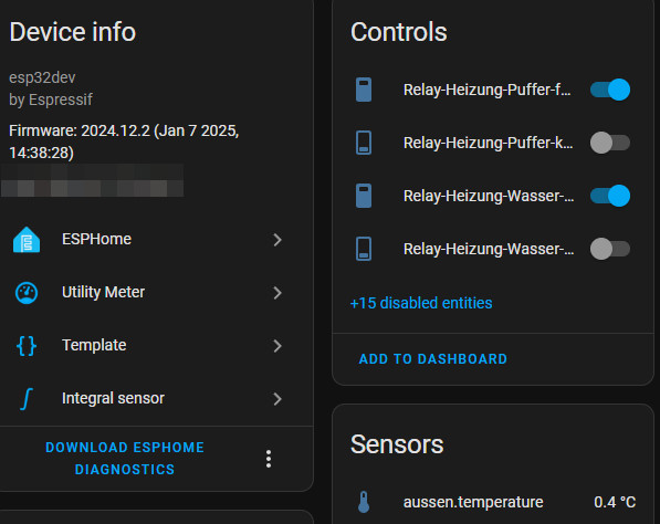
I have created scripts for the individual states so that the switching operations of the relays can be addressed more easily:


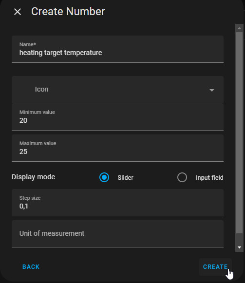
Helper for the desired room temperature
I have created a "number" helper so that the desired room temperature can be conveniently adjusted in the Home Assistant interface:


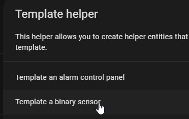
Helper: Template sensor: Potential surplus and weather forecast
To make the HA automation react more effectively to a PV surplus, I have created a customized template sensor helper:
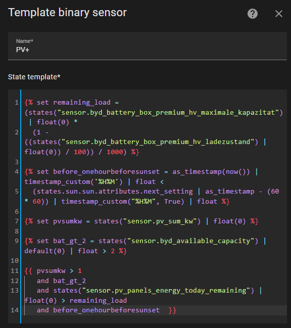
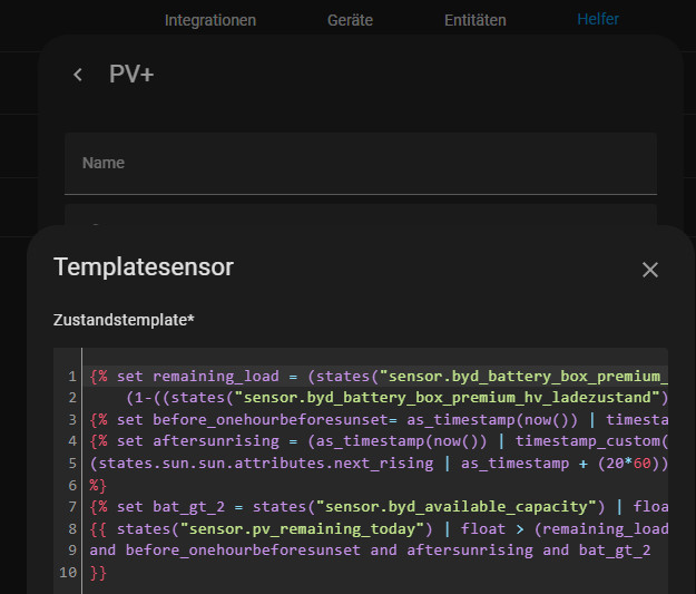
{% set remaining_load = (states("sensor.byd_battery_box_premium_hv_maximale_kapazitat") | float(0) *
  (1 - ((states("sensor.byd_battery_box_premium_hv_ladezustand") | float(0)) / 100)) / 1000) %}

{% set before_onehourbeforesunset = as_timestamp(now()) | timestamp_custom('%H%M') | float <
  (states.sun.sun.attributes.next_setting | as_timestamp - (60 * 60)) | timestamp_custom("%H%M", True) | float %}

{% set pvsumkw = states("sensor.pv_sum_kw") | float(0) %}

{% set bat_gt_2 = states("sensor.byd_available_capacity") | default(0) | float > 2 %}

{{ pvsumkw > 1
   and bat_gt_2
   and states("sensor.pv_panels_energy_today_remaining") | float(0) > remaining_load
   and before_onehourbeforesunset  }}
The template sensor switches to on when over 1kW is produced by the PV system (pvsumkw >1), the PV battery level is at least 2 kWh (bat_gt_2) and the PV forecast for the remaining day is greater than the remaining capacity of the battery (states("sensor.pv_remaining_today") | default(0) | float > remaining_load ). Ok, I can see that this sentence is difficult to digest, perhaps an example will help: Assuming the 10 kWh battery is 50% charged, 5 kWh are still missing until it is full. If the PV forecast for the remaining day is greater than 5 kWh, the template triggers: There is a potential surplus and the target temperature of the rooms is raised via the following automation. This means that the heating can be activated even before the battery is 100% charged. And if the PV forecast is correct, the battery will still be fully charged later that day. I originally used the service "Forecast.Solar" and "energy_forecast_today_remaining" for the control, but have since replaced this with a mix of weather forecast and the previous day's yield data: in the template: "sensor.pv_panels_energy_today_remaining". If there is interest in this, I will write a separate article. For more information on automation, see: Home Assistant automation - possibilities & basics.
Power plug instead of Ohmpilot?
In addition to the heat pump, a Zigbee socket enables the activation of a heating element in the boiler and thus higher hot water temperatures. In order not to overload the socket, I connected the heating element with only 2kW: functionally, at least for hot water preparation, a low-cost replacement for the Fronius Ohmpilot.The following page can be used to calculate the amount of energy required for water heating: Online energy calculator: electric power vs. heat pump.
Automation goal: Control the heat pump for heating and hot water as well as the heating rod, depending on the PV surplus
After recreating and revising the automation several times, here is my final version, somewhat simplified:

The automation is started every 15 minutes, which has the advantage that a restart of Home Assistant has no effect on the automation:

For a faster response, the time could be shortened, or more triggers could be used for certain events.
I have grouped the actions thematically into hot water preparation and room heating:
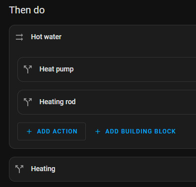
Thanks to the triggers directly in the ESP-Home project and the previously created scripts and template sensors, the logic in the automation remains relatively clear:
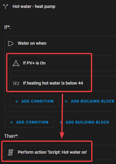
Hot water (DHW heat pump)
The ESP switches off when the target temperature is reached and prevents the hot water from cooling down completely. The automation only has to determine the start time for hot water preparation. To determine the optimum time, I use the previously created template sensor for the PV surplus (PV+) and use the "Hot water on" script as the action.
Optional: Heating rod (WW heating rod)
The logic for the heating rod enables higher hot water temperatures, which increases the chance that the hot water is heated when the sun is shining and more hot water is available in the evening or at night. Of course, this only makes sense if too much electricity is produced, as the heating rod is not as efficient as the heat pump:
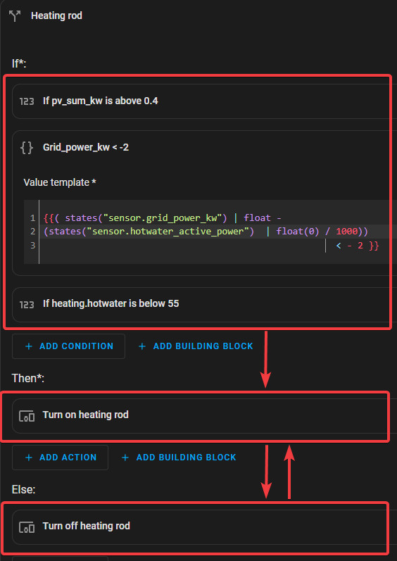
The heating rod becomes active when more than 2kW is fed into the grid: "Grid_power_kw < -2". 2kW. If the heating element is switched on, it reduces the surplus, so use a value template at this point to deduct its consumption.
{{( states("sensor.grid_power_kw") | float -
(states("sensor.hotwater_active_power") | float(0) / 1000))
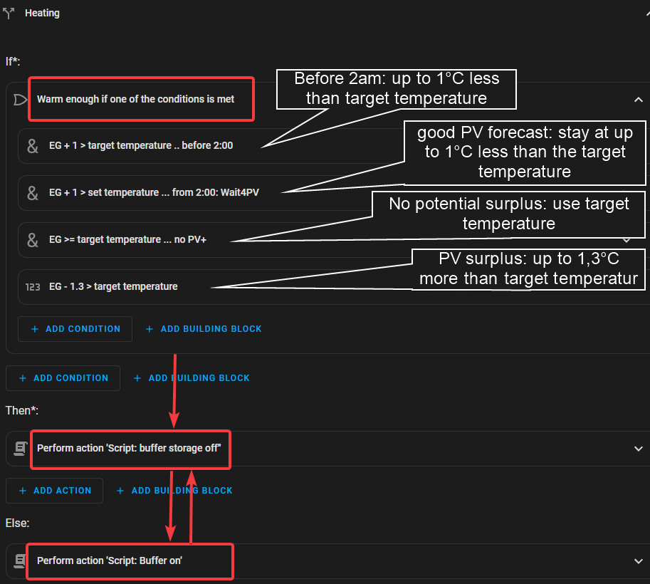
< - 2 }}Control heating (buffer)
The room heating logic is based on criteria that decide whether it is already warm enough. The basis for this is the room temperature and its setpoint temperature: template sensor "heating_room_setpoint_temperature". If the PV system generates enough electricity and the weather forecast permits, the room temperature is raised by up to 1.3 °C above the target temperature using the PV+ sensor (potential surplus). After 21:00 to 2:00 in the morning or if the weather forecast is good, the target temperature may be up to 1 °C below the set target temperature.
Complete (simplified) home assistant automation: YAML
alias: Heating-Automation
description: ""
triggers:
  - minutes: /15
    trigger: time_pattern
conditions: []
actions:
  - alias: Hot Water
    parallel:
      - alias: Heat pump
        if:
          - alias: Water on when
            condition: or
            conditions:
              - condition: state
                entity_id: binary_sensor.pv
                state: "on"
              - condition: numeric_state
                entity_id: sensor.heating_water
                below: 44
        then:
          - data: {}
            action: script.hot_water_on
            continue_on_error: true
      - alias: Heating rod
        if:
          - condition: numeric_state
            entity_id: sensor.pv_sum_kw
            above: 0.4
          - alias: grid_power_kw < -2
            condition: template
            value_template: |-
              {{( states("sensor.grid_power_kw") | float -
              (states("sensor.warmwasser_active_power")  | float(0) / 1000))
                                                                    < - 2 }}
          - condition: numeric_state
            entity_id: sensor.heating_water
            below: 55
        then:
          - type: turn_on
            device_id: 0a9f1a5a5a02fbf55cc577ac6c882b35
            entity_id: switch.water_switch
            domain: switch
        else:
          - type: turn_off
            device_id: 0a9f1a5a5a02fbf55cc577ac6c882b35
            entity_id: d31c0573e9c9d10aa19826e6a7631057
            domain: switch
  - alias: Puffer
    if:
      - alias: Warm enough if one of the conditions is met
        condition: or
        conditions:
          - alias: EG + 1 > target temperature .. before 2:00
            condition: and
            conditions:
              - condition: or
                conditions:
                  - condition: time
                    after: "21:00:00"
                    enabled: true
                  - condition: time
                    before: "02:01:00"
              - condition: numeric_state
                entity_id: sensor.firstfloor.temperature
                above: input_number.heating__target temperature
                value_template: "{{ state.state | float + 1.0 }}"
          - alias: "EG + 1 > target temperature ... ab 2:00: Wait4PV"
            condition: and
            conditions:
              - condition: numeric_state
                entity_id: sensor.firstfloor.temperature
                above: input_number.heating__target_temperature
                value_template: "{{ state.state | float + 1.0 }}"
              - condition: numeric_state
                entity_id: sensor.pv_panels_energy_today_remaining
                above: 20
          - alias: EG >= target temperature ... kein PV+
            condition: and
            conditions:
              - alias: PV+ nicht True
                condition: not
                conditions:
                  - condition: state
                    entity_id: binary_sensor.pv
                    state: "on"
              - condition: numeric_state
                entity_id: sensor.firstfloor.temperature
                above: input_number.heating__target temperature
                value_template: "{{ state.state | float + 0.01 }}"
          - condition: numeric_state
            entity_id: sensor.firstfloor.temperature
            above: input_number.heating__target temperature
            value_template: "{{ state.state | float - 1.3 }}"
            alias: EG - 1,3 > target temperature
    then:
      - data: {}
        action: script.buffer_tank_off
    else:
      - action: script.buffer_tank_on
        data: {}
mode: parallel
trace:
  stored_traces: 100
max: 10
In practice after more than a year of operation → PV self-consumption: 75% degree of self-sufficiency
The automation only really works when the sun is shining: on days when sufficient PV electricity is generated (in green), the heating (in yellow) can be started during the day. If the PV forecast is low, the automation allows the set target temperature (22.5 °C in my case) to be reached after 2 a.m., which means that the heating is activated earlier. If the PV forecast is good, the automation waits until the sun is shining. Here is another example of a few days with 100 % self-consumption including battery status:

For the last 365 days, the energy distribution of my house in Home Assistant looks like this:


Conclusion
Controlling the heating is a simple and cost-effective way of increasing the PV system 's self-consumption. If the boiler or buffer storage tank is heated during the day, the energy does not have to be purchased again at night: This not only benefits PV systems without an electricity storage unit, but can also reduce the load on the battery, which may even be slightly smaller.
Admittedly, my setup is far from plug-and-play, and the automation only worked after some tuning. However, anyone who likes to work with automatic processes can really let off steam with ESP-Home and Home Assistant and really save electricity.
 ({{pro_count}})
{{percentage}} % positive
 ({{con_count}})
THANK YOU for your review!
Questions / Comments
(sorted by rating / date) [all comments (best rated first)]
[2 additional Comments in Deutsch]
Thank you for sharing your work!
I also have an old heating pump that I want to make a bit smarter. But I don't have PV, batteries or any buffer to the heating system. I think I will start by reading temperatures and power consumption to see how it actually operates with its own automation. Then I might add room temperature sensors and output a fake median value to the heat pump.