PV modules in winter: Calculating voltage vs. current

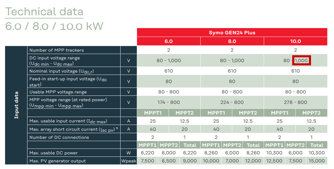
One thing I became aware of by commissioning my balcony power plant is the importance of the voltage and current ratings of the panels: the PV panels used in my balcony power plant deliver a very low voltage 24.8 (Vmp) and in return a high current of up to 16.51A (Imp). When comparing the performance data with some inverters, I found that current inverters for the most part cannot handle more than 13A and would limit the maximum peak power. The Fronius Gen24 as an example can handle 25A on one MPP tracker, but only 12.5A on the second, which would lower the maximum possible power when using the panels on the 2 strings.
Attention: The maximum possible number of modules is limited by the temperature coefficient.
For planning purposes, the open circuit voltage of the modules is crucial. Especially at low temperatures the voltage could become a problem, because the voltage of the modules with decreasing temperature is higher than the specified open circuit voltage. As a concrete example, a Udc max of 1000 volts is given for the Fronius Gen24.
Source: https://www.fronius.com/~/downloads/Solar%20Energy/Datasheets/SE_DS_Fronius_Symo_GEN24Plus_EN.pdf.
As an example, the open circuit voltage when using Meyer Burger White 390 PV panels is : 44.5 V.
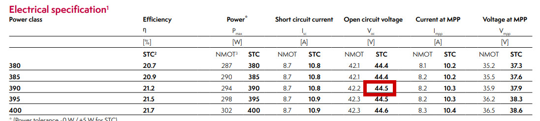
The STC column reflects the standard test conditions: solar radiation of 1000W/m² at a cell temperature of 25°C.
For my system, I have planned 19 modules per string, resulting inan open circuit voltage of 44.5Voc * 19 panels = 845.5V, at an ambient temperature of 25°C (according to STC). According to the data sheet, the inverter can handle Udc max 1000V, so everything is in the green range.
If the temperature drops, the voltage increases by the temperature coefficient Voc ß: -0.234% / K
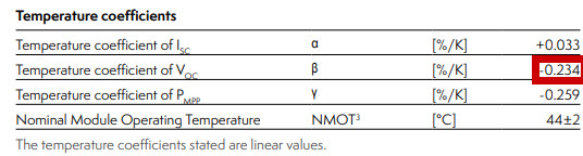
Converted to an ambient temperature of -10 °C (35 °C less than the 25 °C STC temperature), the voltage would be 35 °C x 0.234 %/K = 8.19 % higher than specified: 44.5 Voc * 1.0819 V = 48.14445 Voc / module; with 19 modules: 914.74 V. In theory, the voltage of 1000 V Udc max specified by the inverter is not a problem.
Finally, a brief look at the current values:
At high temperatures, the voltage decreases, but the current increases. Accordingly, the maximum current for an assumed 70°C would be 10.3A * ((70°C-25°C) x 0.033α)% = 10.45 A. The maximum current Idc max for the Fronius GEN24 is specified as 12.5 A for the second MPPT. Although this value can be exceeded without destroying the inverter, it cannot process more than 12.5 A, which can lead to a reduction in performance with certain panels.
Re-measured with a multimeter and thermometer
I have measured the voltage of 19 panels in series with a multimeter: this is 786 V at 36°C under the module. I used an Aquara Zigbee sensor to measure the temperature.
According to the data sheet, the voltage drops by 0.234% per °C. At 11°C difference (36°C panel temperature - 25°C STC temperature) by 11 °C x 0.234 %/K =2.574 %.
The open-circuit voltage per panel at 36°C would therefore be 44.5V (open-circuit STC) * 1-(1 + 0.02574%) (11°C x 0.234%) = 43.35 V.
During a measurement in winter: Outside temperature of 4°C in the shade, the open-circuit voltage of the multimeter shows at 833V. This value corresponds to the voltage value when the inverter is switched on. The calculated voltage with the STC values would be 844.85V. If I use the NMOT values, which should be closer to the real conditions, the calculated voltage is 839.32V. This also coincides with the highest recorded voltage of my east-west system, which was 838 volts. To make it easier to calculate the values, I have put together an online calculator:
Online calculator
Installation / Details
Calculate result
Conclusion
The selection of the inverter and the appropriate PV panels is essential for optimal operation. Especially for PV modules with a current higher than 13A, the maximum possible peak power could never be reached when using some inverters. On the other hand, high voltages limit the maximum possible number of PV panels in a string. On the voltage side, sufficient buffer should be planned so that the inverter is not overloaded at low temperatures. For general planning of a PV system, see also: PV - Considerations - Planning - Implementation and Fronius Gen24 Commissioning in practice: Step by step
 ({{pro_count}})
{{percentage}} % positive
 ({{con_count}})